Visible to Intel only — GUID: joc1463335304047
Ixiasoft
Intel® Stratix® 10 Devices and Transceiver Channels
PCB Stackup Selection Guideline
Recommendations for High Speed Signal PCB Routing
FPGA Fan-out Region Design
CFP2/CFP4 Connector Board Layout Design Guideline
QSFP+/zSFP/QSFP28 Connector Board Layout Design Guideline
SMA 2.4-mm Layout Design Guideline
Tyco/Amphenol Interlaken Connector Design Guideline
Electrical Specifications
Document Revision History for AN 766: Intel® Stratix® 10 Devices, High Speed Signal Interface Layout Design Guideline
Option 1: Via-In-Pad Topology
Option 2: Dog-bone with GND Cutout at BGA Pad Topology
Option 3: Micro-via Topology
GND Cutout Under BGA Pads in Fan-out Configuration
Comparison of Dog-bone with GND Cutout Under the BGA and Via-in-Pad Configurations
Trace Shape Routing at the BGA Void Area (Tear Drop Configuration)
Visible to Intel only — GUID: joc1463335304047
Ixiasoft
Sweeping Void Width only on the First GND Plane Under the Capacitor
Keeping the via anti-pad radius fixed while adjusting the void width on the first GND plane under the AC capacitors also impacts the structure's impedance.
Figure 40. Differential Return Loss and TDR Impedance Performances for 0201 AC Capacitors by Various GND Cutout Widths
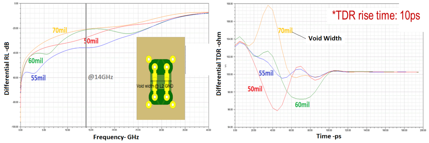
Changing the void width from 50 mil to 70 mil impacts the structure's impedance and return loss. A 55 mil void width is the optimum solution for this case and results in the least mismatching.