Visible to Intel only — GUID: lsj1512069950950
Ixiasoft
5.3.3. The GPIO Tab
The GPIO tab allows you to interact with all the general purpose user I/O components on your board. You can read DIP switch settings, turn LEDs on or off and detect push button presses.
Figure 13. The GPIO Tab
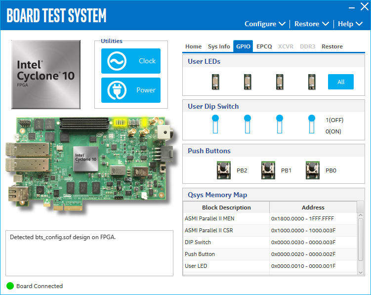
The following sections describe the controls on the GPIO tab.
User DIP Switch
The read-only User DIP Switch control displays the current positions of the switches in the user DIP switch bank (SW1). Change the switches on the board to see the graphical display change.
User LEDS
The User LEDs control displays the current state of the user LEDS. Toggle the LED buttons to turn the board LEDs on or off.
Push Buttons
Read only control displays the current state of the board user push buttons. Press a push button on the board to see the graphical display change accordingly.
Qsys Memory Map
The Qsys memory map control shows the memory map of the bts_config.sof design running on your board.