Visible to Intel only — GUID: sej1498240174263
Ixiasoft
Add Clock, Reset, and Avalon-MM components
Add Pre-Built Systems and Memory Test Microcore Components
Export Signals, Set Base Address Assignments, and Connect Memory Tester Interface Components
Resolve Interface Requirements and Value Mismatches
Replace the memory_tester_subsystem Generic Component
Synchronize IP Results
Visible to Intel only — GUID: sej1498240174263
Ixiasoft
Export Signals, Set Base Address Assignments, and Connect Memory Tester Interface Components
To export signals, set base address assignments, and connect components, perform the following steps:
- To export the Avalon Memory Mapped Master interface for Pattern Writer, in the Export column double-click the row adjacent to the Avalon Memory Mapped Master and type write_master.
- To export the Avalon Memory Mapped Master interface for Pattern Reader, in the Export column, double-click the row adjacent to the Avalon Memory Mapped Master and type read_master.
- Make connections for the system based on the following table:
Table 5. Memory Tester Interface Component Connections Source Compont/Signal Target Component/Signal clk/out_clk - reset/clk
- mm_bridge/clk
- pattern_generator_subsystem/clk
- pattern_checker_subsystem/clk
- pattern_writer/clock
- pattern_reader/clock
- ram_test_controller/clock
reset/out_reset - mm_bridge/reset
- pattern_generator_subsystem/reset
- pattern_checker_subsystem/reset
- pattern_writer/reset
- pattern_reader/reset
- ram_test_controller/reset
mm_bridge/m0 - pattern_generator_subsystem/slave
- pattern_checker_subsystem/slave
- ram_test_controller/csr
pattern_generator_subsystem/st_data_out - pattern_writer/st_data
pattern_reader/st_data - pattern_checker_subsystem/st_data_in
ram_test_controller/read_command - pattern_reader/command
ram_test_controller//write command - pattern_writer/command
- Assign base addresses for Avalon Memory Mapped Slave interfaces:
- In the Base column, click the value for slave signal of the pattern_generator_subsystem component and type 0000.
- In the Base column, click the value for slave signal of the pattern_checker_subsystem component and type 1000.
- In the Base column, click the value for csr signal of the ram_test_controller component and type 800.
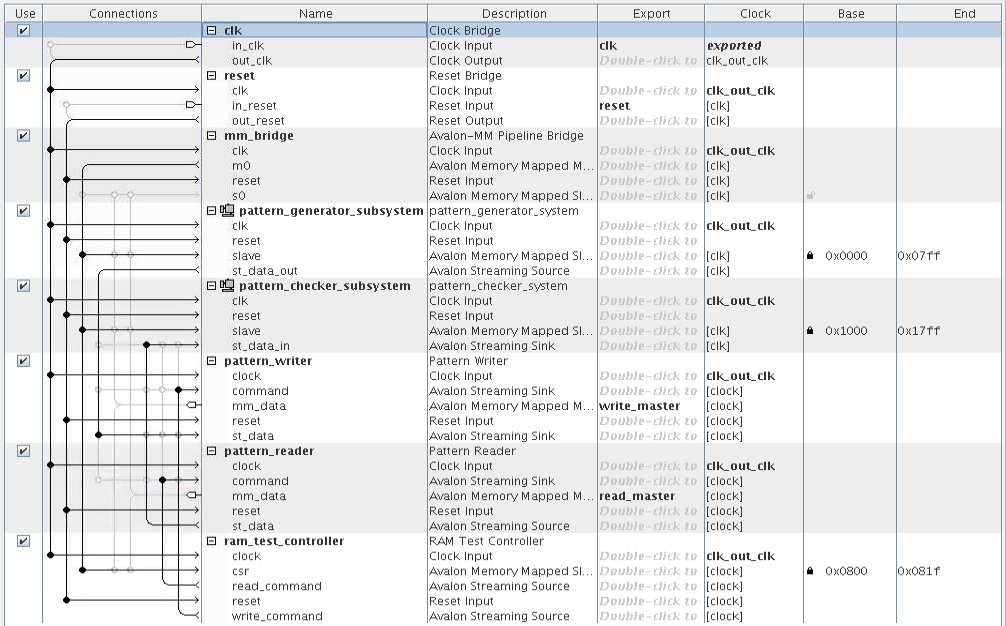
The following figure shows the completed system:Figure 32. Connections and Base Address Values for the memory_tester_sybsystem