Visible to Intel only — GUID: mij1548189456191
Ixiasoft
1. E-Tile Transceiver PHY Overview
2. Implementing the Transceiver PHY Layer
3. E-Tile Transceiver PHY Architecture
4. Clock Network
5. PMA Calibration
6. Resetting Transceiver Channels
7. Dynamic Reconfiguration
8. Dynamic Reconfiguration Examples
9. Register Map
10. Debugging E-Tile Transceiver Links
A. E-Tile Channel Placement Tool
B. PMA Direct PAM4 30 Gbps to 57.8 Gbps Implementation
C. Signal Detect Algorithm
D. Detailed Steps for Reconfiguring from Mission Mode to Channel Protection Mode
E. Detailed Steps for Reconfiguring from Channel Protection Mode to Mission Mode
F. Hold Timing Violation
2.2.1. General and Datapath Parameters
2.2.2. PMA Parameters
2.2.3. Core Interface Options
2.2.4. PMA Interface
2.2.5. PMA Adaptation Parameters
2.2.6. Reed Solomon Forward Error Correction (RS-FEC) Parameters
2.2.7. Reset Parameters
2.2.8. Dynamic Reconfiguration Parameters
2.2.9. Deskew Logic
2.2.10. Port Information
2.2.11. PLL Mode
2.2.12. Simplex Support
3.1.1. Transmitter PMA
3.1.2. Receiver PMA
3.1.3. PMA Tuning
3.1.4. Duplex Adaptation Flow
3.1.5. RX Simplex Adaptation Flow
3.1.6. Dynamic Reconfiguration Adaptation Flow
3.1.7. Loopback modes
3.1.8. PMA Interface
3.1.9. TX PMA Bonding
3.1.10. Unused Transceiver Channels
3.1.11. Low Power Mode (LPM)
3.1.10.1. Unused Transceiver Channels in a Used Tile
3.1.10.2. Unused Transceiver Channels in Completely Unused Tiles
3.1.10.3. Unused Transceiver Channels in High-Speed PAM4 Mode
3.1.10.4. Reconfiguring from Mission Mode to Channel Protection Mode
3.1.10.5. Reconfiguring from Channel Protection Mode to Mission Mode
4.2.1. Single 25 Gbps PMA Direct Channel (with FEC) Within a Single FEC Block
4.2.2. Single 10 Gbps PMA Direct Channel (without FEC)
4.2.3. Four 25 Gbps PMA Direct Channel (with FEC) within a Single FEC Block
4.2.4. PMA Direct 25 Gbps x 4 (FEC Off)
4.2.5. PMA Direct 10.3125 Gbps x 4
4.2.6. PMA Direct 100GE Gbps (25 Gbps x 4) (FEC On)
4.2.7. PMA Direct 100GE PAM4 (50 Gbps x 2) (Aggregate FEC On)
4.2.8. PMA Direct High Data Rate (FEC Off)
6.1. When Is Reset Required?
6.2. How Do I Reset?
6.3. Reset Block Architecture
6.4. PMA Analog Reset
6.5. High Level Specification
6.6. Master-Slave Clocking Option 2 Reset Details
6.7. Quartus® Prime Instantiated Transceiver Reset Sequencer
6.8. Block Diagrams
6.9. Interfaces
6.10. Resetting Transceiver Channels Revision History
7.1. Dynamically Reconfiguring Channel Blocks
7.2. Dynamic Reconfiguration Maximum Data Rate Switch
7.3. Interacting with the Dynamic Reconfiguration Interface
7.4. Unsupported Features
7.5. Reading from the Dynamic Reconfiguration Interface
7.6. Writing to the Dynamic Reconfiguration Interface
7.7. Multiple Reconfiguration Profiles
7.8. Arbitration
7.9. Recommendations for PMA Dynamic Reconfiguration
7.10. Steps to Perform Dynamic Reconfiguration
7.11. PMA Attribute Details
7.12. Dynamic Reconfiguration Flow for Special Cases
7.13. Ports and Parameters
7.14. Embedded Debug Features
7.15. Timing Closure Recommendations
7.16. Transceiver Register Map
7.17. Loading IP Configuration Settings
7.18. Dynamic Reconfiguration Revision History
8.1. Reconfiguring the Duplex PMA Using the Reset Controller in Automatic Mode
8.2. PRBS Usage Model
8.3. PMA Error Injection
8.4. PMA Receiver Equalization Adaptation Usage Model
8.5. User-Defined Pattern Example
8.6. Configuring the Attenuation Value (VOD)
8.7. Configuring the Post Emphasis Value
8.8. Configuring pretap1 Values
8.9. Inverting TX Polarity for the PMA Driver
8.10. Inverting RX Polarity for the PMA Driver
8.11. Configuring a PMA Parameter Tunable by the Adaptive Engine
8.12. Configuring a PMA Parameter Using Native PHY IP
8.13. Enabling Low Power Mode for Multiple Channels
8.14. Initializing an RX
8.15. Resetting the RX Equalization
8.16. Dynamic Reconfiguration Examples Revision History
9.2.1. 0x0001: PMA Enable/Disable
9.2.2. 0x0002: PMA PRBS Settings
9.2.3. 0x0003: Data Comparison Set Up and Start/Stop
9.2.4. 0x0005: TX Channel Divide By Ratio
9.2.5. 0x0006: RX Channel Divide By Ratio
9.2.6. 0x0008: Internal Serial Loopback and Reverse Parallel Loopback Control
9.2.7. 0x000A: Receiver Tuning Controls
9.2.8. 0x000E: RX Phase Slip
9.2.9. 0x0011: PMA TX/RX Calibration
9.2.10. 0x0013: TX/RX Polarity and Gray Code Encoding
9.2.11. 0x0014: TX/RX Width Mode
9.2.12. 0x0015: TX Equalization
9.2.13. 0x0017: Error Counter Reset
9.2.14. 0x0018: Status/Debug Register
9.2.15. 0x0019: Status/Debug Register Next Write Field
9.2.16. 0x001A: Status/Debug Register Next Read Field
9.2.17. 0x001B: TX Error Injection Signal
9.2.18. 0x001C: Incoming RX Data Capture
9.2.19. 0x001E: Error Count Status
9.2.20. 0x0020: Electrical Idle Detector
9.2.21. 0x002B: RX Termination and TX Driver Tri-state Behavior
9.2.22. 0x0030: PMA Mux Clock Swap
9.2.23. 0x0126: Read Receiver Tuning Parameters
9.2.24. Reading and Writing PMA Analog Parameters Using Attributes
9.2.24.1. Reading PMA Analog Parameters
9.2.24.2. Updating PMA Analog Parameters
9.2.24.3. Loading Parameters into the Receiver
9.2.24.4. Fixing Parameter Values
9.2.24.5. Reading NRZ/PAM4 Eye Height
9.2.24.6. Enabling and Disabling Electrical Idle Detector Filtering and Reading Electrical Idle Detector Status
9.2.24.7. Initial Adaptation Effort Levels
9.5.1. rsfec_top_clk_cfg
9.5.2. rsfec_top_tx_cfg
9.5.3. rsfec_top_rx_cfg
9.5.4. tx_aib_dsk_conf
9.5.5. rsfec_core_cfg
9.5.6. rsfec_lane_cfg
9.5.7. tx_aib_dsk_status
9.5.8. rsfec_debug_cfg
9.5.9. rsfec_lane_tx_stat
9.5.10. rsfec_lane_tx_hold
9.5.11. rsfec_lane_tx_inten
9.5.12. rsfec_lane_rx_stat
9.5.13. rsfec_lane_rx_hold
9.5.14. rsfec_lane_rx_inten
9.5.15. rsfec_lanes_rx_stat
9.5.16. rsfec_lanes_rx_hold
9.5.17. rsfec_lanes_rx_inten
9.5.18. rsfec_ln_mapping_rx
9.5.19. rsfec_ln_skew_rx
9.5.20. rsfec_cw_pos_rx
9.5.21. rsfec_core_ecc_hold
9.5.22. rsfec_err_inj_tx
9.5.23. rsfec_err_val_tx
9.5.24. rsfec_corr_cw_cnt (Low)
9.5.25. rsfec_corr_cw_cnt (High)
9.5.26. rsfec_uncorr_cw_cnt (Low)
9.5.27. rsfec_uncorr_cw_cnt (High)
9.5.28. rsfec_corr_syms_cnt (Low)
9.5.29. rsfec_corr_syms_cnt (High)
9.5.30. rsfec_corr_0s_cnt (Low)
9.5.31. rsfec_corr_0s_cnt (High)
9.5.32. rsfec_corr_1s_cnt (Low)
9.5.33. rsfec_corr_1s_cnt (High)
10.1. E-Tile Transceiver Toolkit Overview
10.2. E-Tile Transceiver Debugging Flow Walkthrough
10.3. Modifying the Design to Enable E-Tile Transceiver Debug
10.4. Programming the Design into an Intel FPGA
10.5. Loading the Design in the E-Tile Transceiver Toolkit
10.6. Verifying E-Tile Hardware Connections
10.7. Running Transceiver Tests
10.8. Controlling PMA Analog Settings
10.9. Debugging E-Tile Transceiver Links Revision History
B.1. Building Blocks and Considerations
B.2. Starting a New Quartus® Prime Pro Edition Design
B.3. Selecting the Configuration Clock Source
B.4. Instantiating the Transceiver Native PHY IP
B.5. Instantiating the In-system Sources and Probes Intel® FPGA IP
B.6. Making the Top Level Connection
B.7. Assigning Pins
B.8. Bringing up the Board
B.9. Debug Tools
B.10. PMA Direct PAM4 30 Gbps to 57.8 Gbps Implementation Revision History
Visible to Intel only — GUID: mij1548189456191
Ixiasoft
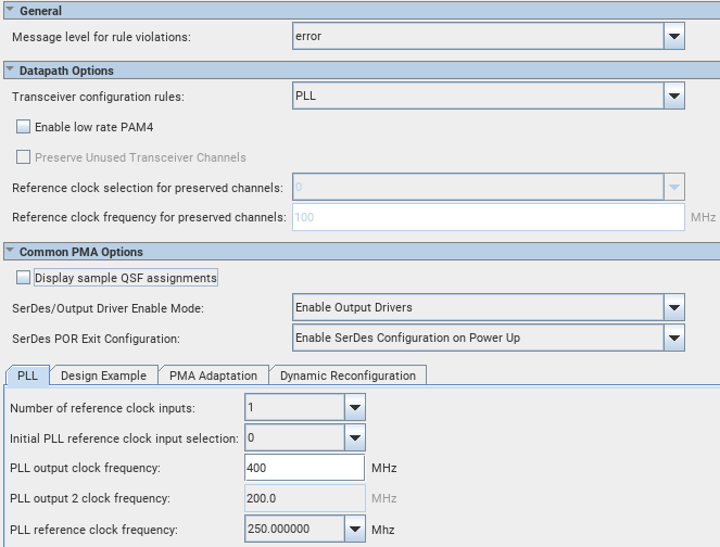
2.2.11. PLL Mode
PLL mode is a configuration of the E-tile transceiver Native PHY IP core that configures the E-tile transceiver as a PLL. It is used for external EMIB clocking configurations (see the use case in Four 25 Gbps PMA Direct Channel (with FEC) within a Single FEC Block ). It does not support dynamic reconfiguring between PLL and other Transceiver Configuration Rules.
After a transceiver channel is used in PLL mode, it cannot be used for a usual transceiver operation. You have to connect the output of the Native PHY IP core in PLL mode to the respective transceiver input.
Figure 42. E-Tile Native PHY IP PLL Mode
| Parameter | Value | Description |
|---|---|---|
| Number of reference clock inputs | 1, 2, 3, 4, 5 | Specifies the desired number of reference clocks. The Native PHY IP core presents up to five clock inputs. |
| Initial TX reference clock input selection | Based on the number of reference clock input | Specifies the initially selected PLL reference clock input. This indicates the starting clock input selection used for this configuration when dynamically switching between multiple TX reference clock inputs. |
| PLL output clock frequency | 100 - 1000 MHz | Specifies the PLL output frequency in units of MHz. |
| PLL output 2 clock frequency | Output from the PLL. pll_clkout2 frequency = 0.5 * pll_clkout1 frequency |
Specifies the PLL output frequency for output 2 in units of MHz. |
| PLL reference clock frequency | Refer to the Device Data Sheet. | Selects the reference clock frequency for the PLL. |
PLL output clock (pll_clkout) and PLL output 2 clock (pll_clkout2) are asynchronous (no phase relationship) to each other and to any other clock output from the Native PHY IP. You need to take the required precautions to do any data transfers between the two clocks.
| Port Name | Direction | Clock Domain | Width | Description |
|---|---|---|---|---|
| pll_refclk0 pll_refclk1 pll_refclk2 pll_refclk3 pll_refclk4 |
Input | N/A | 1 bit for each channel | Reference clock for the PLL. |
| pll_locked | Output | reconfig_clk | 1 bit for each channel | Locked status signal of the PLL. When you use the PLL channel as a clock source to the transceiver channel through external EMIB clocking:
|
| tx_serial_data | Output | N/A | 1 bit for each channel | The tx_serial_data port is only used to assign the location of the PLL channel. It is not an active port for transmitting data.10 |
| pll_clkout1 pll_clkout2 |
Output | N/A | 1 bit for each channel | Output from the PLL. pll_clkout2 frequency = 0.5 * pll_clkout1 frequency |
10 If you are targeting a channel that is not bonded out on a device package (for example, a PTP channel), you can leave tx_serial_data unconnected and make the location assignment to the HSSIXCVR component of the channel. For example:
set_location_assignment HSSIXCVR_4T9A18 -to <path>|xcvr_native_s10_etile_0|g_xcvr_native_insts[0].ct3_xcvr_native_inst|inst_ct3_xcvr_channel|inst_ct3_hssi_xcvr