Visible to Intel only — GUID: vam1566429083509
Ixiasoft
1. About the P-tile Avalon® Intel® FPGA IPs for PCI Express
2. IP Architecture and Functional Description
3. Parameters
4. Interfaces
5. Advanced Features
6. Troubleshooting/Debugging
7. Document Revision History for the P-tile Avalon® Memory-mapped Intel FPGA IP for PCI Express User Guide
A. Configuration Space Registers
4.1. Overview
4.2. Clocks and Resets
4.3. Avalon® -MM Interface
4.4. Serial Data Interface
4.5. Hard IP Status Interface
4.6. Interrupt Interface
4.7. Hot Plug Interface (RP Only)
4.8. Power Management Interface
4.9. Configuration Output Interface
4.10. Hard IP Reconfiguration Interface
4.11. PHY Reconfiguration Interface
A.2.1. Intel-Defined VSEC Capability Header (Offset 00h)
A.2.2. Intel-Defined Vendor Specific Header (Offset 04h)
A.2.3. Intel Marker (Offset 08h)
A.2.4. JTAG Silicon ID (Offset 0x0C - 0x18)
A.2.5. User Configurable Device and Board ID (Offset 0x1C - 0x1D)
A.2.6. General Purpose Control and Status Register (Offset 0x30)
A.2.7. Uncorrectable Internal Error Status Register (Offset 0x34)
A.2.8. Uncorrectable Internal Error Mask Register (Offset 0x38)
A.2.9. Correctable Internal Error Status Register (Offset 0x3C)
A.2.10. Correctable Internal Error Mask Register (Offset 0x40)
Visible to Intel only — GUID: vam1566429083509
Ixiasoft
6.2.4. Using the P-Tile Debug Toolkit
The following sections describe the different tabs and features available in the Debug Toolkit.
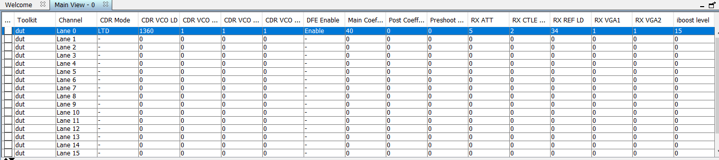
A. Main View
The main view tab lists a summary of the transmitter and receiver settings per channel for the given instance of the PCIe IP.
The following table shows the channel mapping when using bifurcated ports.
| Toolkit Channel | X16 Mode | 2X8 Mode | 4x4 Mode |
|---|---|---|---|
| Lane 0 | Lane 0 | Lane 0 | Lane 0 |
| Lane 1 | Lane 1 | Lane 1 | Lane 1 |
| Lane 2 | Lane 2 | Lane 2 | Lane 2 |
| Lane 3 | Lane 3 | Lane 3 | Lane 3 |
| Lane 4 | Lane 4 | Lane 4 | Lane 0 |
| Lane 5 | Lane 5 | Lane 5 | Lane 1 |
| Lane 6 | Lane 6 | Lane 6 | Lane 2 |
| Lane 7 | Lane 7 | Lane 7 | Lane 3 |
| Lane 8 | Lane 8 | Lane 0 | Lane 0 |
| Lane 9 | Lane 9 | Lane 1 | Lane 1 |
| Lane 10 | Lane 10 | Lane 2 | Lane 2 |
| Lane 11 | Lane 11 | Lane 3 | Lane 3 |
| Lane 12 | Lane 12 | Lane 4 | Lane 0 |
| Lane 13 | Lane 13 | Lane 5 | Lane 1 |
| Lane 14 | Lane 14 | Lane 6 | Lane 2 |
| Lane 15 | Lane 15 | Lane 7 | Lane 3 |
B. Toolkit Parameters
The Toolkit parameters window has 2 sub-tabs.
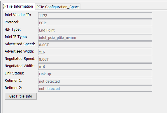
B.1. P-Tile Information
This lists a summary of the P-Tile PCIe IP parameter settings in the PCIe IP Parameter Editor when the IP was generated, as read by the P-Tile Debug Toolkit when initialized.
When using bifurcated ports, you will see all the P-Tile information for each port for which the Debug Toolkit has been enabled.
All the information is read-only.
Use the Get P-tile Info button to read the settings.
| Parameter | Values | Descriptions |
|---|---|---|
| Intel Vendor ID | 1172 | Indicates the Vendor ID as set in the IP Parameter Editor. |
| Protocol | PCIe | Indicates the Protocol. |
| HIP Type | Root Port, End Point | Indicates the Hard IP Port type. |
| Intel IP Type | intel_pcie_ptile_ast, intel_pcie_ptile_avmm | Indicates the IP type used. |
| Advertised speed | Gen3, Gen4 | Indicates the advertised speed as configured in the IP Parameter Editor. |
| Advertised width | x16, x8, x4 | Indicates the advertised width as configured in the IP Parameter Editor. |
| Negotiated speed | Gen3, Gen4 | Indicates the negotiated speed during link training. |
| Negotiated width | x16, x8, x4 | Indicates the negotiated link width during link training. |
| Link status | Link up, link down | Indicates if the link (DL) is up or not. |
| Retimer 1 | Detected, not detected | Indicates if a retimer was detected between the Root Port and the Endpoint. |
| Retimer 2 | Detected, not detected | Indicates if a retimer was detected between the Root Port and the Endpoint. |
Figure 39. Example of P-Tile Parameter Settings
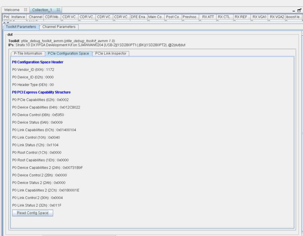
B.2. PCIe Configuration Space
This lists a summary of the P-Tile PCIe configuration settings of the PCIe configuration space registers, as read by the P-Tile Debug Toolkit when initialized.
All the information is read-only.
Use the Read cfg space button to read the settings.
Figure 40. Example of P-Tile PCIe Configuration Settings
C. Channel Parameters
The channel parameters window allows you to monitor and control the transmitter and receiver settings for a given channel. It has the following 2 sub-windows.
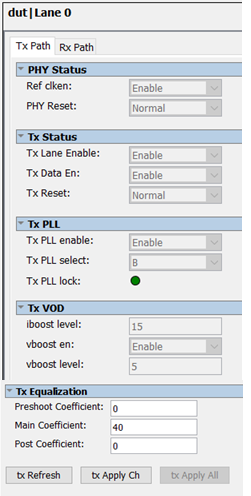
C.1. TX Path
This tab allows you to monitor and control the transmitter settings for the channel selected. Use the TX Refresh button to read the settings, TX Apply Ch to apply the settings to the selected channel, and TX apply all to apply the settings to all channels.
| Parameters | Values | Descriptions | |
|---|---|---|---|
| PHY Status | Refclk enable | Enable, Disable | Indicates reference clock is enabled for the PHY. Enable: Reference clock is enabled for the PHY. Disable: Reference clock is disabled for the PHY. |
| PHY reset | Normal, Reset | Indicates the PHY is in reset mode. Normal: PHY is out of reset. Reset: PHY is in reset. |
|
| TX Status | TX Lane enable | Enable, Disable | Indicates if TX lane is enabled in the PHY. Enable: TX lane is enabled in the PHY. Disable: TX lane is disabled in the PHY. |
| TX Data enable | Enable, Disable | Indicates if TX driver is enabled and serial data is transmitted. Enable: TX driver for the corresponding lane is enabled. Disable: TX driver for the corresponding lane is disabled. |
|
| TX Reset | Normal, Reset | Indicates if TX (TX datapath, TX settings) is in reset or normal operating mode. Normal: TX is in normal operating mode. Reset: TX is in reset. |
|
| TX PLL | TX PLL enable | Enable, Disable | Indicates if the TX PLL is powered on or powered down. This is dependent on the PLL selected as indicated by TX PLL select.
There is one set of PLLs per Quad. The TX path of each channel reads out the PLL status corresponding to that Quad.
Enable: TX PLL is powered on. Disable: TX PLL is powered down. |
| TX PLL select | PLLA: Gen1/Gen2 PLLB: Gen3/Gen4 |
Indicates which PLL is selected.
There is one set of PLLs per Quad. The TX path of each channel reads out the PLL status corresponding to that Quad.
|
|
| TX PLL lock | Green, Red | Indicates if TX PLL is locked. This is dependent on the PLL selected as indicated by TX PLL select.
There is one set of PLLs per Quad. The TX path of each channel reads out the PLL status corresponding to that Quad.
Green: TX PLL is locked. Red: TX PLL is not locked. |
|
| TX VOD | Iboost level | Gen3: 15 Gen4: 15 |
Indicates the transmitter current boost level when the TX amplitude boost mode is enabled. |
| Vboost en | Gen3 Enable Gen4 Enable |
Indicates if the TX swing boost level is enabled. Enable: TX swing boost is enabled. Disable: TX swing boost is disabled. |
|
| Vboost level | Gen3: 5 Gen4: 5 |
Indicates the TX Vboost level. | |
| TX Equalization | Pre-shoot coefficient | Gen3: 20 (Preset 8) Gen4: 0 (Preset 0) |
Indicates transmitter driver output pre-emphasis (pre-shoot coefficient). |
| Main coefficient | Gen3: 30 (Preset 8) Gen4: 30 (Preset 0) |
Indicates transmitter driver output pre-emphasis (main coefficient). |
|
| Post coefficient | Gen3: 20 (Preset 8) Gen4: 40 (Preset 0) |
Indicates transmitter driver output pre-emphasis (post coefficient). |
Figure 41. Example of Transmitter Settings
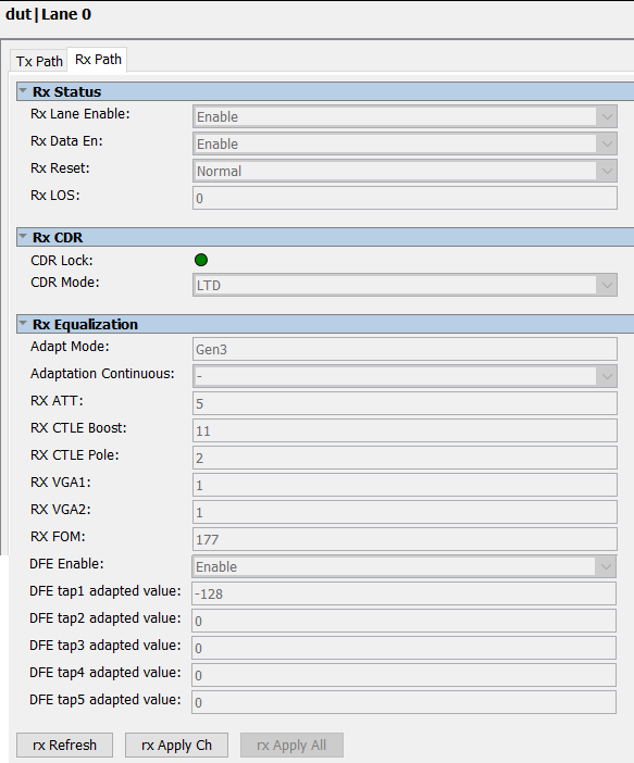
C.1. RX Path
This tab allows you to monitor and control the receiver settings for the channel selected. Use the RX Refresh button to read the settings, RX Apply Ch to apply the settings to the selected channel, and RX apply all to apply the settings to all channels.
| Parameters | Values | Descriptions | |
|---|---|---|---|
| RX Status | RX Lane enable | Enable, Disable | Indicates if RX lane is enabled in the PHY. Enable: RX lane is enabled in the PHY. Disable: RX lane is disabled in the PHY. |
| RX Data enable | Enable, Disable | Indicates if RX driver is enabled and serial data is transmitted. Enable: RX driver for the corresponding lane is enabled. Disable: RX driver for the corresponding lane is disabled. |
|
| RX Reset | Normal, Reset | Indicates if RX (RX datapath, RX settings) is in reset or normal operating mode. Normal: RX is in normal operating mode. Reset: RX is in reset. |
|
| RX LOS | <1,0> | Indicates if the receiver has lost the signal. 1: Receiver loss of signal. 0: Receiver has a data signal. |
|
| RX CDR | CDR Lock | Green, Red | Indicates the CDR lock state. Green: CDR is locked. Red: CDR is not locked. |
| CDR Mode | Locked to Reference (LTR), Locked to Data (LTD) | Indicates the CDR lock mode. LTR: CDR is locked to reference clock. LTD: CDR is locked to data. |
|
| RX Equalization | Adapt Mode | Gen3: Gen3 adaptation mode. Gen4: Gen4 adaptation mode. |
Indicates the RX adaptation mode. |
| Adapt Continuous | Gen3: 1 Gen4: 1 |
Indicates if the receiver is in continuous adaptation.
|
|
| RX ATT | Gen3: 0 Gen4: 0 |
Indicates the RX equalization attenuation level. |
|
| RX CTLE Boost | Gen3: 12 Gen4: 16 |
Indicates the RX CTLE boost value. |
|
| RX CTLE Pole | Gen3: 2 Gen4: 2 |
Indicates the RX CTLE pole value. |
|
| RX VGA1 | Gen3: 5 Gen4: 5 |
Indicates the RX AFE first stage VGA gain value. |
|
| RX VGA2 | Gen3: 5 Gen4: 5 |
Indicates the RX AFE second stage VGA gain value. |
|
| RX FOM | <0-255> | Indicates the Receiver Figure of Merit (FOM) / quality of the received data eye. A higher value indicates better link equalization, with 8'd0 indicating the worst equalization setting and 8'd255 indicating the best equalization setting. |
|
| DFE Enable | Enable, Disable | Indicates DFE adaptation is enabled for taps 1 - 5. Enable: DFE adaptation is enabled for taps 1 - 5. Disable: DFE adaptation is disabled for taps 1 - 5. |
|
| DFE Tap1 adapted value | <-128 to 127> | Indicates the adapted value of DFE tap 1. This is a signed input (two's complement encoded). |
|
| DFE Tap2 adapted value | <-32 to 31> | Indicates the adapted value of DFE tap 2. This is a signed input (two's complement encoded). |
|
| DFE Tap3 adapted value | <-32 to 31> | Indicates the adapted value of DFE tap 3. This is a signed input (two's complement encoded). |
|
| DFE Tap4 adapted value | <-32 to 31> | Indicates the adapted value of DFE tap 4. This is a signed input (two's complement encoded). |
|
| DFE Tap5 adapted value | <-32 to 31> | Indicates the adapted value of DFE tap 5. This is a signed input (two's complement encoded). |
Figure 42. Example of Receiver Settings
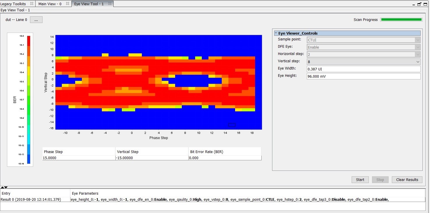
Eye Viewer
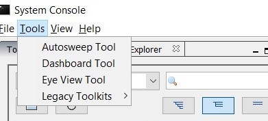
The P-Tile Debug Toolkit supports running eye tests for Intel devices with P-Tile. The Eye Viewer tool allows you to set up and run eye tests, monitoring bit errors.
- In the System Console Tools menu option, click on Eye View Tool.
Figure 43. Opening the Eye Viewer
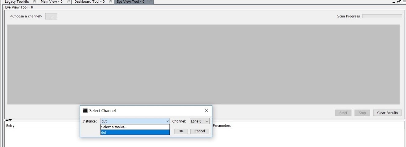
- This will open a new tab Eye View Tool next to the Main View tab. Choose the instance and channel for which you want to run the eye view tests.
Figure 44. Opening the Instance and Channel
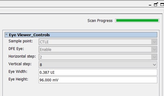
- Choose the eye vertical step setting from the drop-down menu. The eye view tool allows you to choose between vertical step sizes of 1, 2, 4, 8.
Note: The time taken for the eye view tool to draw the eye varies with different vertical step sizes (8 results in a faster eye plot when compared to 1).Figure 45. Choosing the Step Size
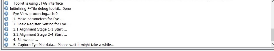
- The messages window displays information messages to indicate the eye view tool's progress.
Figure 46. Eye View Tool Messages
- Once the eye plot is complete, the eye height, eye width and eye diagram are displayed.
Figure 47. Sample Eye Plot