2.3.2. Estimating Power Consumption While Creating the FPGA Design
If your FPGA design is partially complete, you can import the Early Power Estimator (EPE) file (<revision name> _early_pwr.csv) generated by the Intel® Quartus® Prime software into the EPE spreadsheet. After importing the information from the EPE file into the EPE spreadsheet, you can edit the EPE spreadsheet to reflect the device resource estimates for your final design.
| Advantage | Constraint |
|---|---|
|
|
Importing a File
To estimate power consumption with the EPE spreadsheet if your FPGA design is partially complete, you can import a file.
Importing a file saves you time and effort otherwise spent on manually entering information into the EPE. You can also manually change any of the values after importing a file.
Generating the EPE File
To generate the EPE file, follow these steps:
- Compile the partial FPGA design in the Intel® Quartus® Prime software.
- On the Project menu, click Generate Early Power Estimator File to generate the <revision name> _early_pwr.csv in the Intel® Quartus® Prime software.
Importing Data into the EPE Spreadsheet
You must import the EPE file into the EPE spreadsheet before modifying any information in the EPE spreadsheet. Also, you must verify all your information after importing a file.
Importing a file from the Intel® Quartus® Prime software populates all input values that were specified in the Intel® Quartus® Prime software. Alternatively, you can import values exported from an earlier version of the EPE spreadsheet.
Input values imported into the EPE spreadsheet are the values taken from the Intel® Quartus® Prime software as per the design, or the values that were entered into an earlier version of the EPE spreadsheet. After importing, you can manually edit the values in the EPE spreadsheet to suit your changing design requirements.
To import data into the EPE spreadsheet, follow these steps:
- On the Main worksheet of the EPE, click Import CSV.
- Browse to an EPE file generated from the Intel® Quartus® Prime software or an earlier version of the EPE spreadsheet and click Open. The file has the name <revision name> _early_pwr.csv.
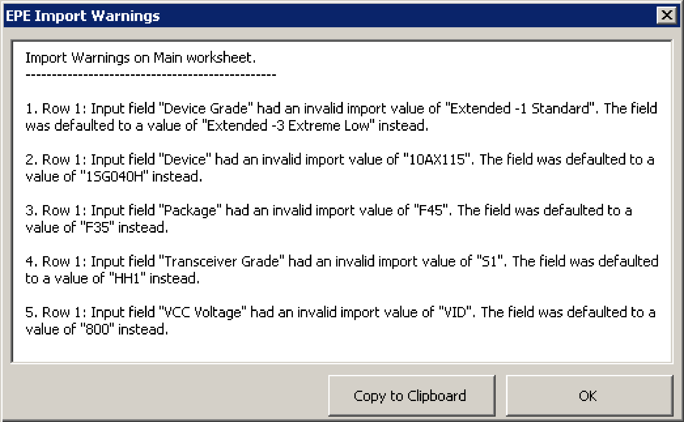
- After the file is imported, the mouse cursor changes from busy to normal. If there are any warnings during the importation, the EPE produces the EPE Import Warnings dialog box. Analyze the warnings carefully to ensure that they are expected. If any of the warnings are unexpected, you must manually modify the corresponding fields in the EPE after the importation is completed. You can copy all warning messages to the clipboard for future reference by clicking Copy to Clipboard. Click OK to dismiss the EPE Import Warnings dialog box.
The following figure shows example warnings that may occur when importing a design from the EPE spreadsheet. The first four error messages indicate that device ordering codes have changed between the two families, so the previous values for Device Grade, Device, Package and Transceiver Grade input fields could not be imported directly, but were set to their default values instead. The last message indicates that the VCC voltage value does not apply to the default device that was selected due to the first four warning messages, so the voltage was set to its default value.
Figure 1. Example Warning Messages During Importation